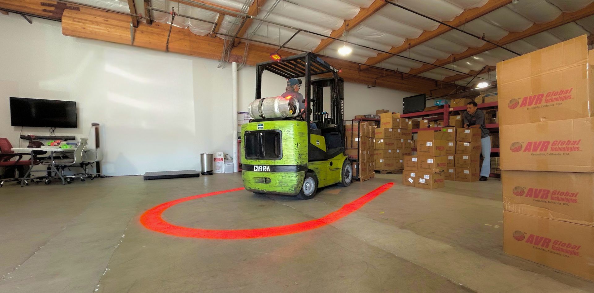
Adding Visual Warning Systems to Existing Equipment

Rene Lightfoot • August 20, 2026

Share this article

Adding Visual Warning Systems to Existing Equipment

Adding a visual warning system to an existing fleet involves more than selecting a light.


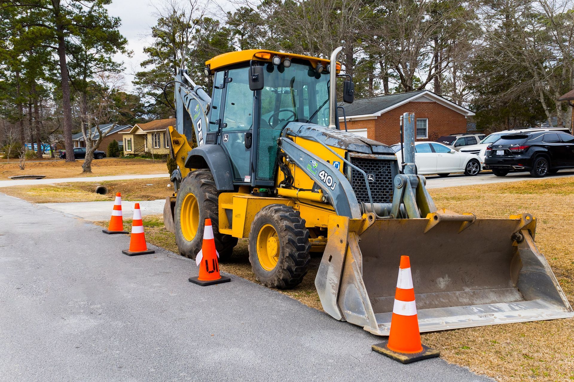
Equipment type, electrical architecture, mounting position, cable routing, environmental exposure, serviceability, and fleet standardization can all affect how a warning-light system should be integrated.


Planning these details before installation can make it easier to develop a repeatable solution across multiple machines.

Start With the Equipment

Before selecting a configuration, identify the equipment that will receive the system.

Useful information includes:

  • Manufacturer and model
  • Equipment type
  • Battery or system voltage
  • Number of units
  • Available mounting locations
  • Distance from the mounting location to the power source
  • Existing connectors or accessory-power connections
  • Operating environment

Photos of the equipment and proposed mounting locations can also help identify potential installation challenges.

Select the Warning Area

The desired visual effect influences the lighting configuration.

A single U-Light may be appropriate when the objective is to create one U-shaped projected boundary.

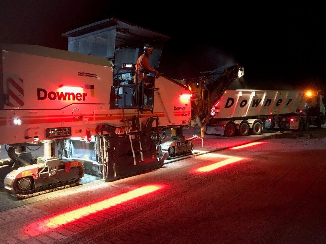
Applications requiring independently positioned projections around multiple sides of a machine may benefit from a multi-light configuration.

The equipment geometry and operating environment should determine the configuration rather than attempting to use one universal layout across every application.

Engineering Support for Custom Applications

Guardian Glow systems can be supported by custom cable assemblies developed around equipment-specific installation requirements.


Providing equipment information, voltage, desired warning area, mounting-location photos, and approximate cable-routing distances gives the engineering team a starting point for identifying an appropriate configuration.


For larger fleet or OEM programs, the same process can be used to develop repeatable solutions for multiple units.


Technical Note: Final electrical connection, circuit protection, mounting method, cable construction, and installation should be confirmed for the specific equipment and operating environment.

Sources:

National Institute for Occupational Safety and Health — Construction Equipment Visibility

National Institute for Occupational Safety and Health — Creating Blind Area Diagrams: Manual Method

National Institute for Occupational Safety and Health — Preventing Struck-by Injuries in Construction


Important: Projected warning lighting is a supplemental visual-awareness measure. It does not eliminate equipment blind areas or replace spotters, barriers, traffic-control plans, training, PPE, or other controls required for the application.

Recent Posts

By Rene Lightfoot August 20, 2026
Understanding Blind Areas Around Construction Equipment
By Rene Lightfoot August 20, 2026
Forklift & Pedestrian Safety: Improving Visibility Around Mobile Equipment
By Rene Lightfoot August 20, 2026
Warning Lights & Forklift Safety: What OSHA Guidance Actually Says